Accredited testing methods
The accreditation (from the German Accreditation Authority, DAkkS) in accordance with DIN EN ISO/IEC 17025:2018 confirms our competence and quality and identifies us as a reliable partner for medical technology companies and notified bodies.
The accredited test methods are based on the requirements of international standards, considering in particular DIN EN ISO 25539-1:2018, DIN EN ISO 25539-2:2021 as well as relevant ASTM standards. The respective standards are given in the short descriptions of the individual test procedures.
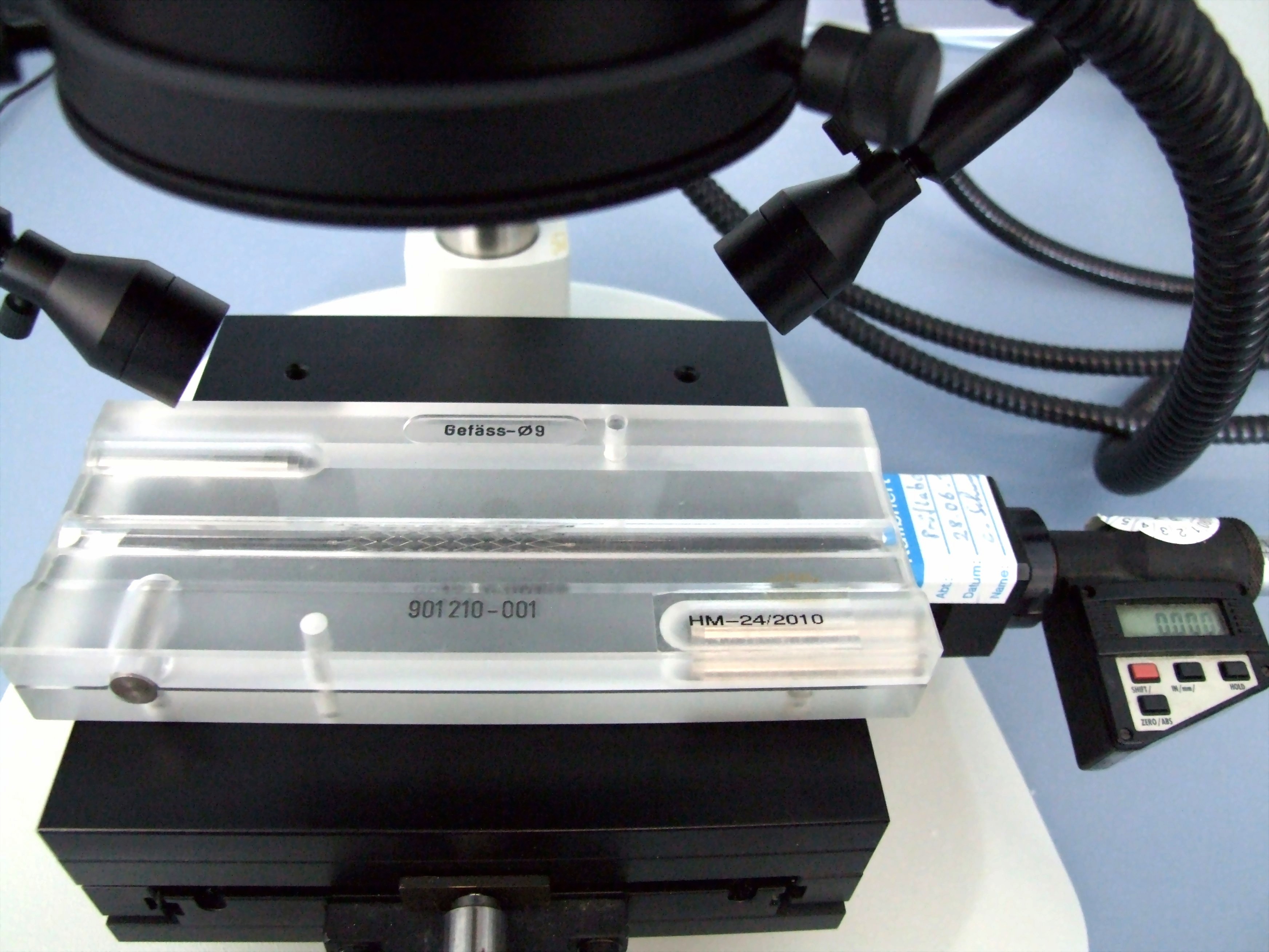
Verification of dimensions
Normative reference of the accredited test procedure:
DIN EN ISO 25539-2:2021, sect. 8.5.1.2, 8.5.2.5.1, 8.5.2.5.3, D.5.2.3, D.5.3.5.1 and D.5.3.5.3
DIN EN ISO 25539-1:2018, sect. 8.5.1.2, 8.5.2.7.1, D.5.1.2 and D.5.2.7.1,
DIN EN ISO 10555-1:2024, sect. 5.1,
DIN EN ISO 10555-4:2023, sect. 4.3,
ASTM F 2081-06 (2023)
For the verification of the dimensions, high precise two axis laser scanners, measurement microscopes with cross table are used as well as digital calipers (depending on the measurement goal).
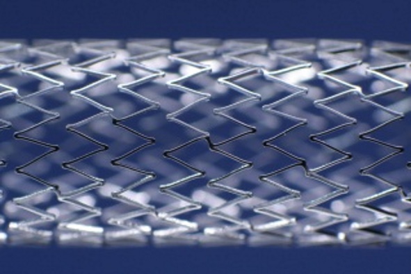
Determination of stent surface
Normative reference of the accredited test procedure:
DIN EN ISO 25539-2:2021, Sect. 8.5.2.4.6, D.5.3.4.6.6,
ASTM F 2081-06 (2017)
This method determines the stent-free surface and the outer stent surface of the stent. The stent-free surface is given as a percentage of the outer stent surface. The density of the stent material has to be provided by the client.
Relation between diameter and inflation pressure, recoil test
Normative reference of the accredited test procedure:
DIN EN ISO 25539-2:2021, sect. 8.5.1.1.4, 8.5.2.5.1, 8.5.2.5.2, 8.5.2.5.3, 8.5.2.5.4 and D.5.3.5.2,
DIN EN ISO 25539-1:2018, sect. 8.5.2.7.2 and D.5.2.7.2,
DIN EN ISO 10555-4:2023, sect. 4.4.4,
ASTM F 2079-09 (2022)
The method contains the testing of expansion behavior of stent systems and catheters (relation of stent diameter and balloon pressure; max. 30 mm in diameter) as well as the measurement of elastic recoil of balloon-expandable stents. Resulting parameters are the dog boning of the balloon, outer diameter and length of the stent depending on the balloon pressure as well as the elastic recoil of the stent.
The outer stent diameter at different pressure steps and the elastic recoil (in mm and %) are provided separately for the distal, central and proximal sections.
Relation between length and diameter
Normative reference of the accredited test procedure:
DIN EN ISO 25539-2:2021, sect. 8.5.2.5.3 and D.5.3.5.3,
DIN EN ISO 25539-1:2018, sect. 8.5.2.7.3 and D.5.2.7.3,
ASTM F2081-06 (2017), sect. 7.2
The change in length is measured as the difference in length between crimped and expanded stent. It is provided as relative value related to the length of the crimped (not expanded) stent. The relating stent diameters are also provided.
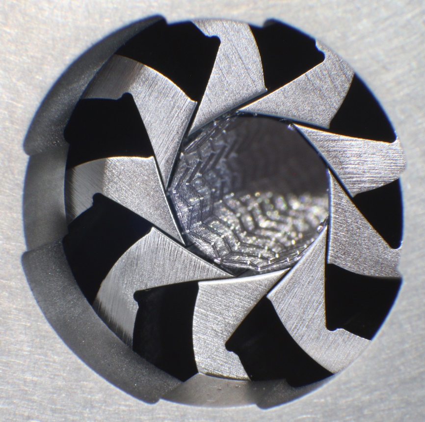
Side branch access of stents
Reference:
internal standard RW-08,
N. Foin et al., Int J Cardiol, 20131
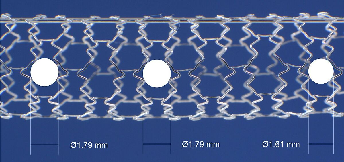
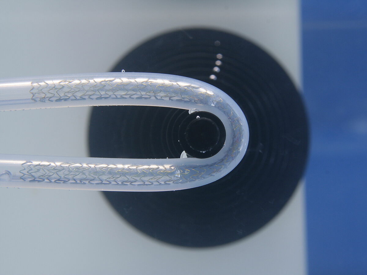
Within this test the expanded stent is investigated with regard to the maximum diameter which allows for a free access through the stent structure.
The access to side branches is of clinical importance during bifurcation stenting.
1 Foin, N.; Torii, R.; Alegria, E.; Sen, S.; Petraco, R.; Nijjer, S. et al. (2013): Location ofside branch access critically affects results in bifurcation stenting: Insights from bench modeling and computational flow simulation. In: International Journal of Cardiology 168(4), S. 3623–3628. DOI: 10.1016/j.ijcard.2013.05.036.
Surface analysis by REM/ESEM
Normative reference of the accredited test procedure:
DIN EN ISO 25539-2:2021, sect. 8.5.2.3 and D.5.3.3,
DIN EN ISO 25539-1:2018, sect. 8.5.2.3 and D.5.2.3,
DIN EN ISO 10555-1:2024, sect. 4.7,
internal standards RW-04, RW-05
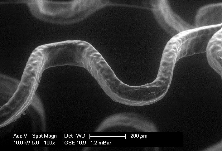
The test method is related to surface analyses with high resolution as they are required after fatigue testing of stents or stent grafts. Depending on the application incident light microscopy or scanning electron microscopy are used. For investigation of both electrically conductive and isolating surfaces the high vacuum mode (HV), the low vacuum mode (LV) as well as the environmental mode (ESEM) can be applied.
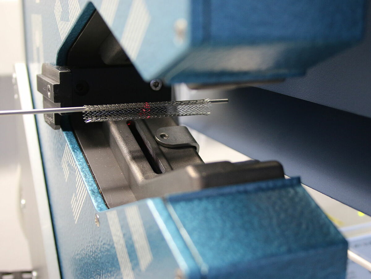
Crush resistance with perpendicular applied load
Normative references of the accredited test procedure:
DIN EN ISO 25539-2:2013, sect. 8.6.2.4, 8.6.2.5
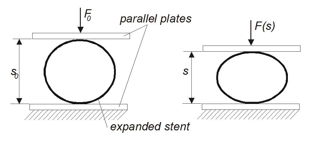
The measurement of crush resistance of stents is used to characterize the mechanical support function of stents if loaded non-radially. It is applicable for self-expanding as well as balloon expandable stents. The method is standardized for application of parallel plates (DIN EN ISO 25539-2:2013, sect. 8.6.2.4) and local compression (DIN EN ISO 25539-2:2013, sect. 8.6.2.5). The test procedures are in accordance to DIN EN ISO 25539-2:2013, sect. D.5.3.5 (parallel plates) or D.5.3.7 (local compression).
Crush resistance with radially applied load (hydraulic pressure)
Normative reference of the accredited test procedure:
DIN EN ISO 25539-2:2021, sect. 8.5.2.4.3
DIN EN ISO 25539-1:2018, sect. 8.5.2.5.3
ASTM F 3067-14(2021), sect. 6.14, 7.4, 8.2
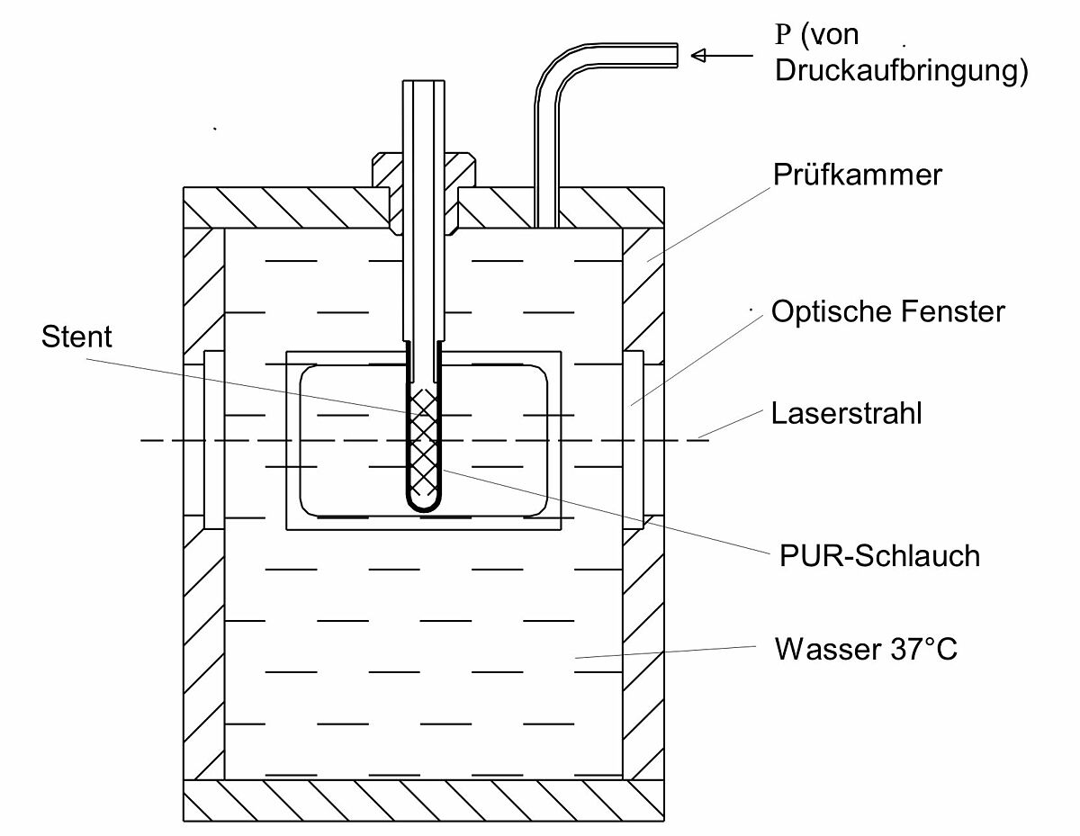
This procedure implies the test of the stability against deformation of stents with radially applied load. The implant diameter change is evaluated as a function of the pressure on the circumference until the complete collapse (collapse pressure).
Crush resistance of balloonexpandable stents under radial loading (segmented head test method)
Normative reference of the accredited test procedure:
DIN EN ISO 25539-2:2021, Abs. 8.5.2.4.3, D.5.3.4.3
DIN EN ISO 25539-1:2018, Abs. 8.5.2.5.3, D.5.2.5.3
ASTM F 3067-14(2021), Abs. 6.12, 7.2, 8.1
This procedure implies the test of the stability against radial deformation of balloon expandable stents. The expanded stent is deformed radially within the segmented head test setup. Radial strength is determined at a pre-defined amount of plastic deformation.
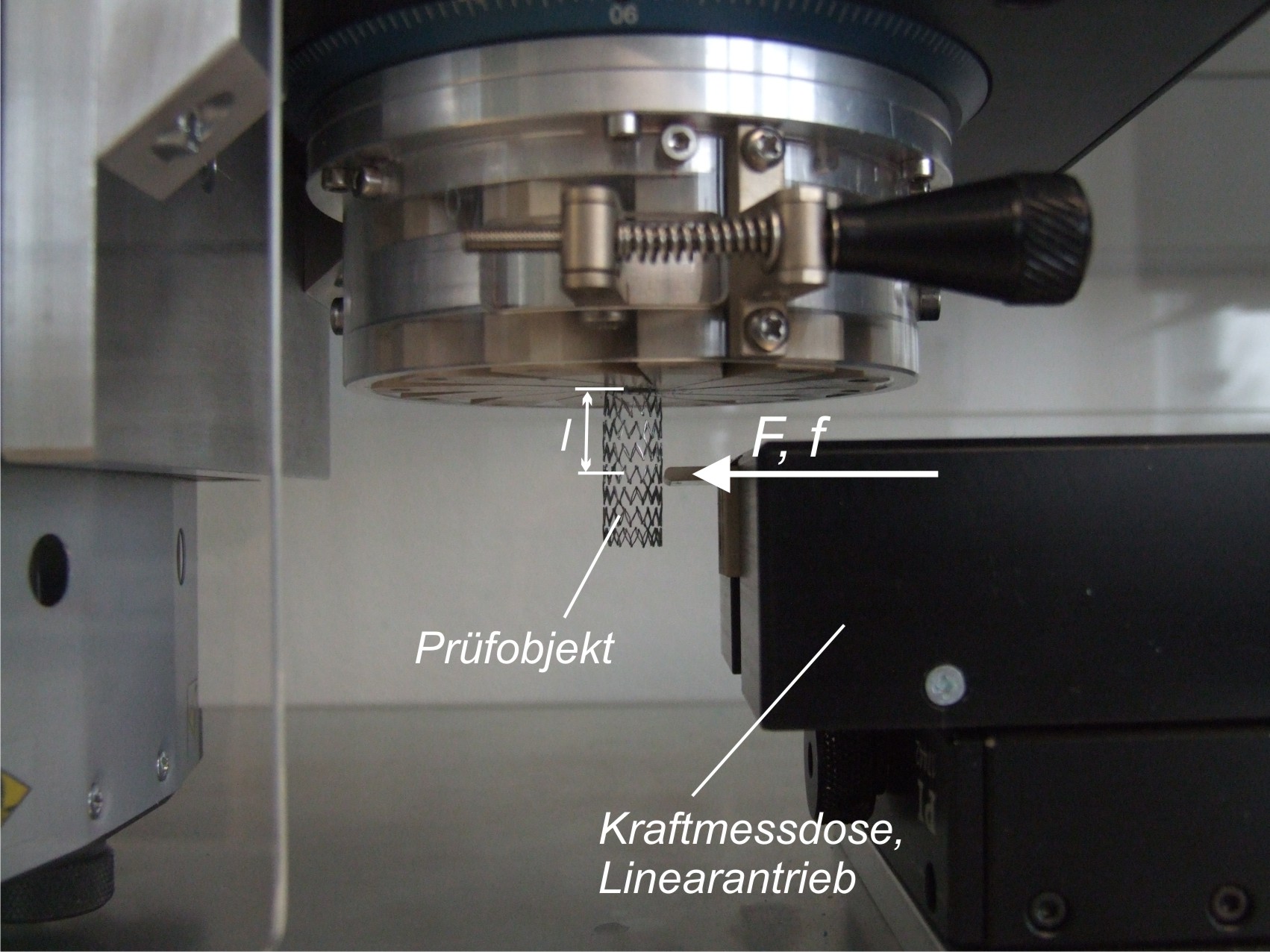
Radial force of self-expanding stents (segmented head test method)
Normative reference of the accredited test procedure:
DIN EN ISO 25539-2:2021, sect. 8.5.2.4.4 and D.5.3.4.4
DIN EN ISO 25539-1:2018, sect. 8.5.2.5.4 and D.5.2.5.4,
ASTM F 3067-14, Sect. 6.12, 7.3, 8.3
The test method determines the radial force of a self-expanding stents as a function of stent diameter via segmented head test apparatus. At lower and upper vessel diameter the length normalized radial force during stent expansion (Chronic Outward Force) as well as during stent compression (Radial Resistive Force) is provided.
Radial force of self-expanding stents (v-block test method)
Normative reference of the accredited test procedure:
DIN EN ISO 25539-2:20212, sect. 8.5.2.4.4
The test method determines the radial force of a self-expanding stents as a function of stent diameter via v-block test apparatus. At lower and upper vessel diameter the length normalized radial force during stent expansion (Chronic Outward Force) as well as during stent compression (Radial Resistive Force) is provided.
2 The current version of DIN EN ISO 25539-2 does not refer to the v-block test method anymore. However, the v-block-test method can be advantageous for stents with very small radial forces.
Bending stiffness of balloon catheters and stent systems
Reference:
internal standard RW-01,
Acta Rad 19663
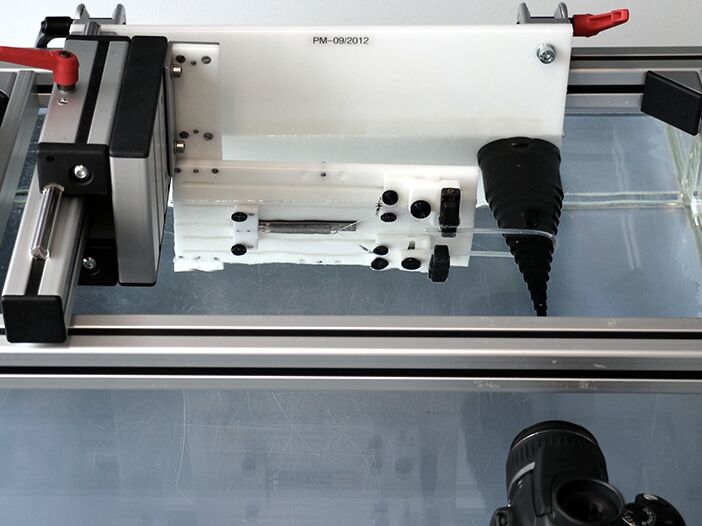
The measurement of bending stiffness of stent systems and PTCA catheters is usually performed in the course of product development or for comparison of commercially available products. A calibrated test setup (2-point bending) is available for the measurement.
3 (1966) I. Mechanical Properties of Catheters, Acta Radiologica: Diagnosis, 4:sup260, 11-22; doi.org/10.1080/05678066609170493
Dislodgement force (balloon-expandable stents)
Normative reference of the accredited test procedure:
DIN EN ISO 25539-2:2021, sect. 8.5.1.3 and D.5.2.4,
DIN EN ISO 25539-1:2018, sect. 8.5.1.3 and D.5.1.3,
ASTM F 2394-07(2017)
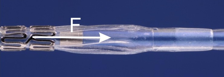
The measurement of dislodgment force is performed to assess the firmness of crimping of balloon-expandable stents. The force is measured which is required to release the stent from its crimped position moving it to distal or proximal direction. Before the test a preconditioning in an anatomical vessel model is performed.
Profile effect/flaring
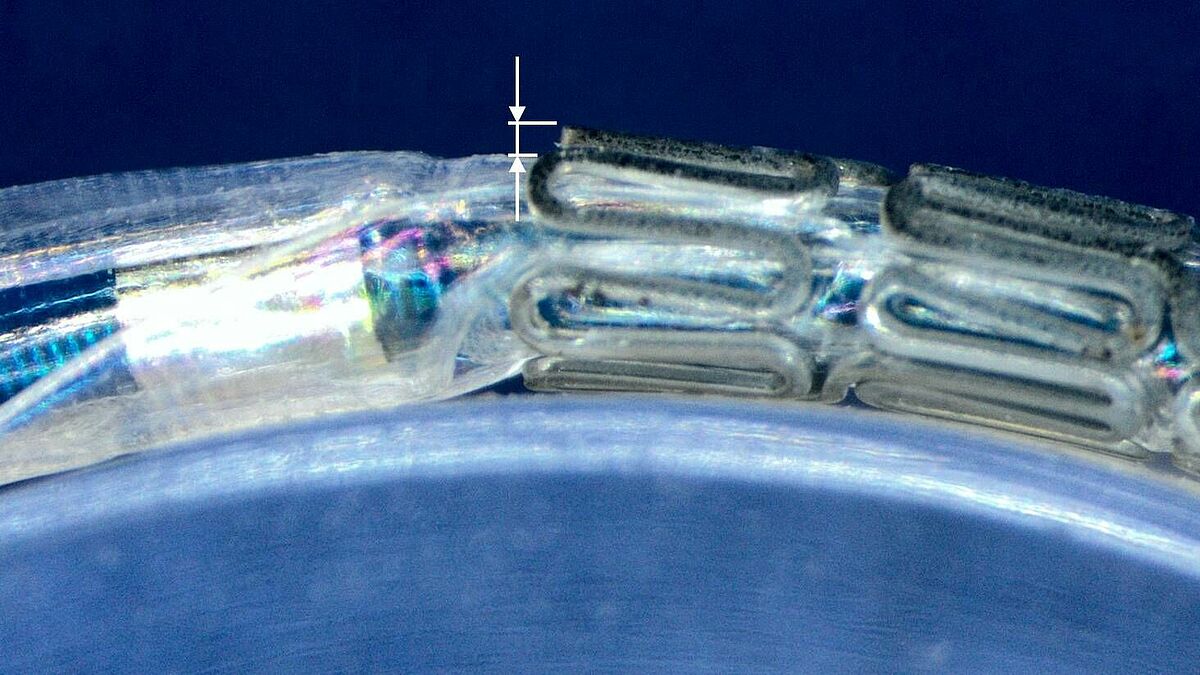
Normative reference of the accredited test procedure:
DIN EN ISO 25539-2:2021, sect. 8.5.1.6 and D.5.2.7
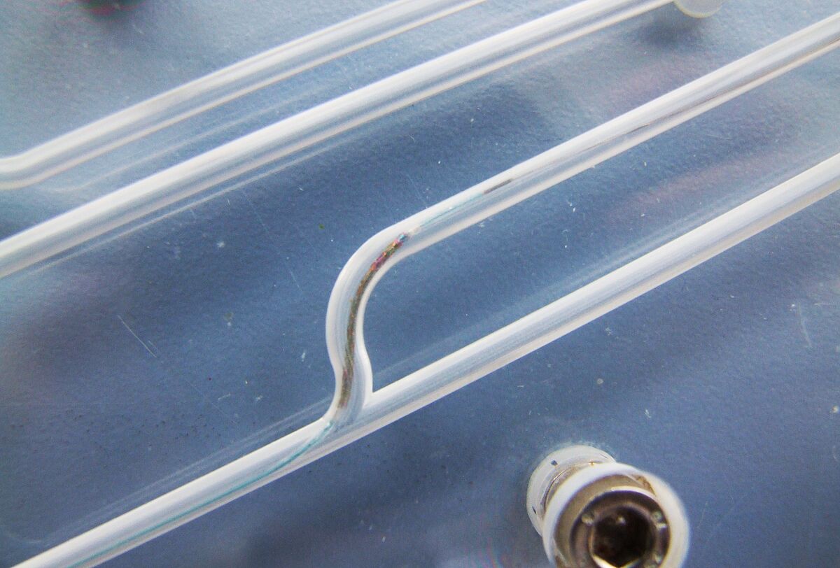
The method measures the distance between the outer diameter of the stent and the adjacent balloon in the original state, after advancing it through an anatomical vessel model and in a state where the system is bent over a clinically relevant radius.
Kink resistance
Normative reference of the accredited test procedure:
DIN EN ISO 25539-2:2021, sect. 8.5.2.4.5 and D.5.3.4.5,
DIN EN ISO 25539-1:2018, sect. 8.5.2.5.5 and D.5.2.5.5
The main goal of the test is to determine the smallest radius of curvature which the stent can withstand without kinking or a lumen reduction of more than 50%. In addition, stent recovery of its original size and shape is determined.
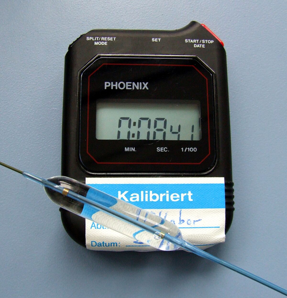
Balloon inflation and deflation time
Normative reference of the accredited test procedure:
DIN EN ISO 25539-2:2021, sect. 8.5.1.1 .1 and D.5.2.2.2
DIN EN ISO 10555-4:2024, sect. 4.4.3 und annex C
The time is measured which is required for balloon deflation is determined which is needed to remove the balloon from the stent or vessel (deflation time). In consultation with the customer the time which is required for balloon expansion with maximum rated balloon pressure (inflation time, according to DIN EN ISO 25539-2:2013, sect, 8.5.2.3) can be measured additionally.
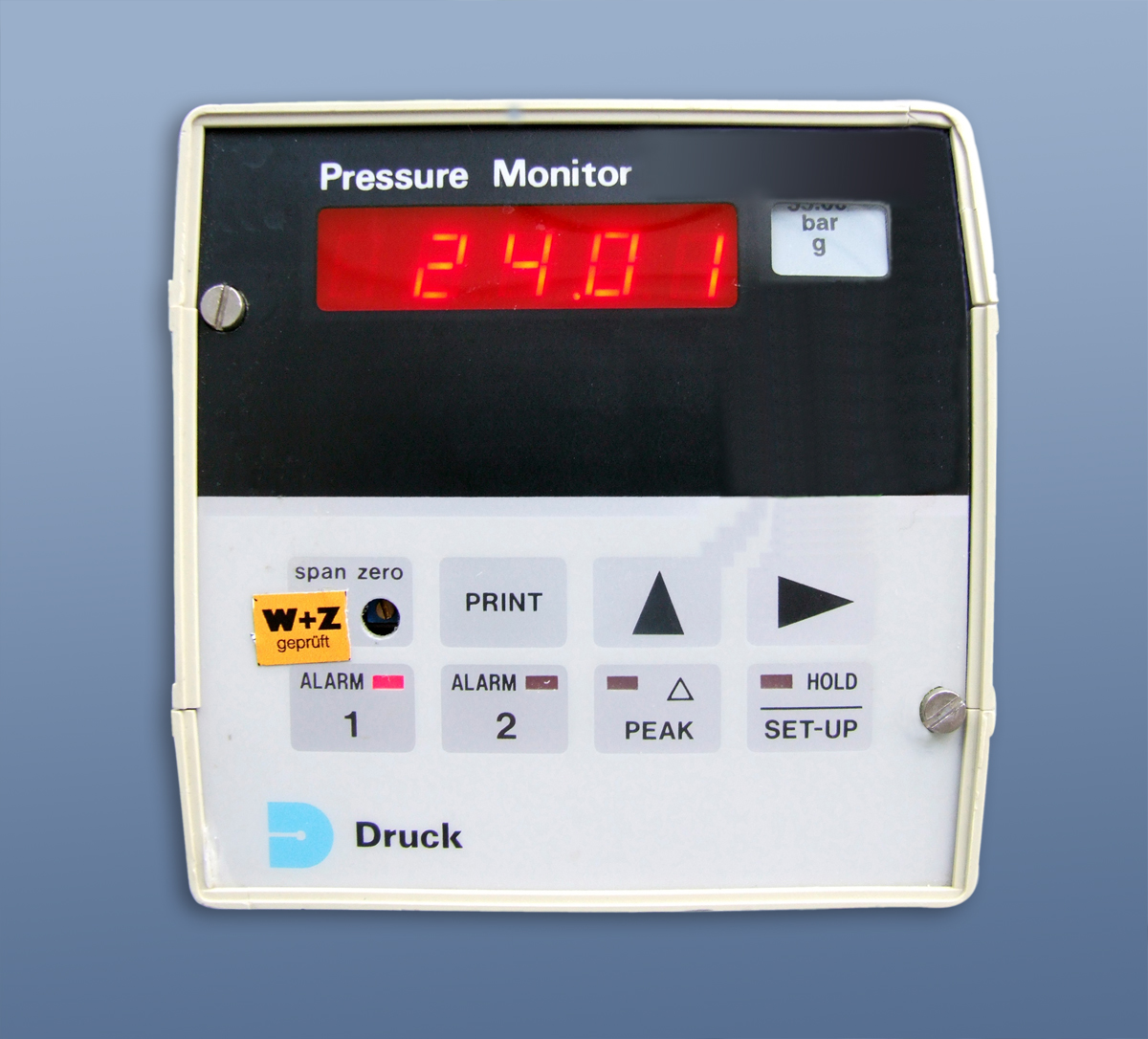
Rated balloon burst pressure
Normative reference of the accredited test procedure:
DIN EN ISO 25539-2:2021, sect. 8.5.1.1.2 and D.5.2.2.3
DIN EN ISO 10555-04:2024, sect. 4.4.1,
ASTM F2079-09 (2022)
The method is applied to determine the burst pressure of PTCA/PTA balloon catheters and stent systems at defined pressure steps from 0 to 30 atm. The calculation of the RBP follows special statistics. The method is in accordance with ASTM F2079-09 (2017).
Design fatigue resistance of balloon
Normative reference of the accredited test procedure:
DIN EN ISO 25539-2:2021, sect. 8.5.1.1.3 and D.5.2.2.4
DIN EN ISO 10555-4:2024, sect. 4.4.2 and annex B
It is the goal to test whether the balloon can resist a determined number of pressure loading cycles up to RBP without damage. The minimum number is 10 cycles.
Simulated use
Normative reference of the accredited test procedure:
DIN EN ISO 25539-2:2021, sect. 8.5.1.7 and D.5.1.7,
DIN EN ISO 25539-1:2018, sect. 8.5.1.5 and D.5.1.5,
DIN EN ISO 10555-4:2024, sect. 4.4.6 and annex F
The testing covers a qualitative assessment of pushability, trackability, torsional strength and bending/kinking of the stent system during insertion. The stent is also expanded and the adaptation to the vessel wall as well as the accuracy of placement are assessed. Different interventions are simulated using specially adapted anatomical models (also in agreement with the customer).
Coating integrity
Normative reference of the accredited test procedure:
DIN EN ISO 25539-2:2021, sect. 8.5.1.5, in part. sect. 8.5.1.5.1 and D.5.2.6 as well as
sect. 8.5.1.5.2,
DIN EN ISO 10555-2024, sect. 4.17,
Ph. Eur. 2.9.19,
USP 788
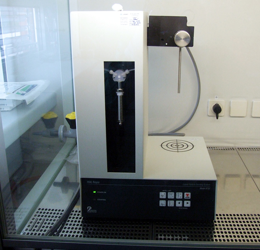
Particle release and the stent surface as well as the coating condition after unimpaired deployment (baseline test), simulated use or fatigue testing are estimated. The released particles were collected in aqueous solutions and are quantified according their size and amount. Furthermore, the surface condition of the stents is assessed by scanning electron microscopy.
Particle release of medical products
Normative reference of the accredited test procedure:
ISO 14708-1:2014, sect. 14.2,
DIN EN ISO 14708-2:2022, sect. 14.2,
Ph. Eur. 2.9.19,
USP 788
The methods covers the testing of particle release from medical products without mechanical loading as well as the assessment according to the limits of DIN EN 45502-2-1:2004, sect. 14.2 and USP 788.
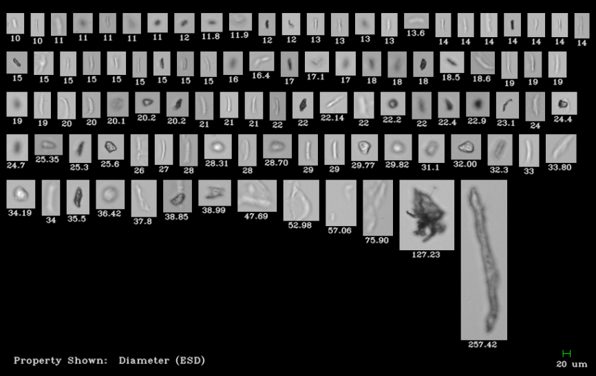
Particle characterization by dynamic image analysis
Normative reference of the accredited test procedure:
In accordance to ASTM E 3060-16, sect. 8, 9, 10,
internal standard RW-06
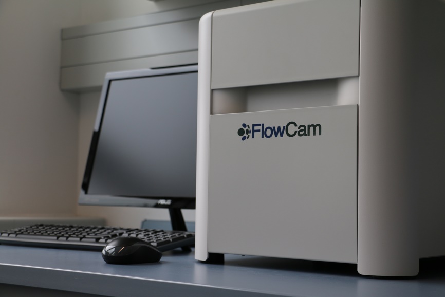
The test procedure enables morphological characterization of particles in liquid suspensions using dynamic image analysis. Dynamic Image Analysis is based on an optical method which takes images of each detected particle and stores it in a data base. Subsequently, the morphology of the particles can be assessed.
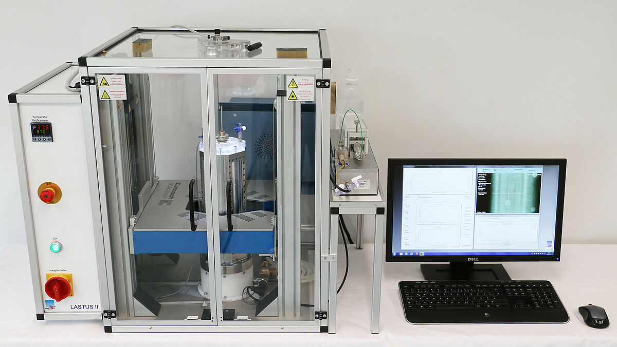
Radial fatigue and duarbility
Normative reference of the accredited test procedure:
DIN EN ISO 25539-2:2021, sect. 8.5.2.3,
DIN EN ISO 25539-1:2018, sect. 8.5.2.3.2,
internal standard RW-02
For verification of durability the stents are exposed to a cyclic radial load of up to 380 mio. load cycles (10 years life-time simulation). Radial fatigue testing can be performed for balloon-expandable as well as for self-expanding stents. The test frequency is identified at one test sample before testing and may be between 40 and 100 Hz. A preconditioning of the stents (simulated use) can be agreed with the customer.
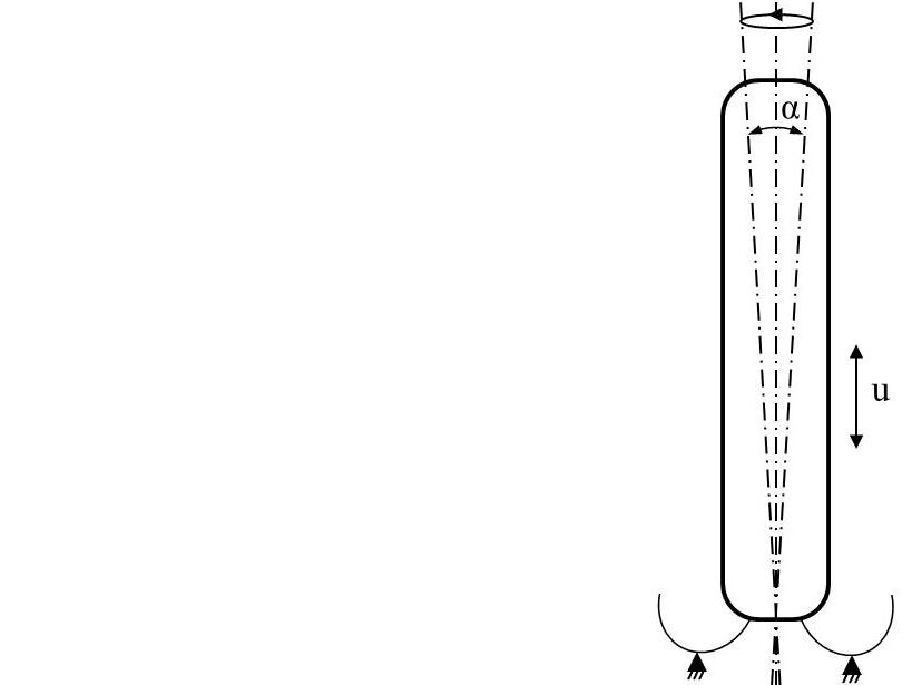
Multiaxial fatigue and durability (axial elongation/compression, bending, torsion)
Normative reference of the accredited test procedure:
DIN EN ISO 25539-2:2021, sect. 8.5.2.3, D.5.3.3.1, D.5.3.3.3, D.5.3.3.4 and D.5.3.3.5
DIN EN ISO 25539-1:2018, sect. 8.5.2.3, D.5.2.3.1, D.5.2.3.4, D.5.2.3.5 and D.5.2.3.6
ASTM F 2942-19,
internal standard RW-03
The scope is to test the durability of self-expanding stents at multiaxial loading conditions. The amplitudes are derived from worst case conditions during SFA stent application (Arteria femoralis superficialis). Axial, bending and torsional deformations are superimposed according to physiological load exposure.
A preconditioning of the stents (simulated use) can be agreed with the customer.
Fatigue testing of fixation elements of implantable leadless pacemakers (iLP)
Normative reference of the accredited test procedure:
internal standard RW-07
considering the fundamental requirements according to ISO 14708-1:2014,
ISO 14708-2:2019, DIN EN ISO 25539-1:2018 and ASTM F3211-17
The durability of fixation elements of implantable leadless pacemakers is tested during cyclic loading.
Determination of physiological loads, durability specifications and relevant test modes is concluded according to ASTM F3211-17, sect. 6.1 to 6.3. The defined test modes are confirmed by literature data resulting in an axial load and a secondary load as tumbling motion.
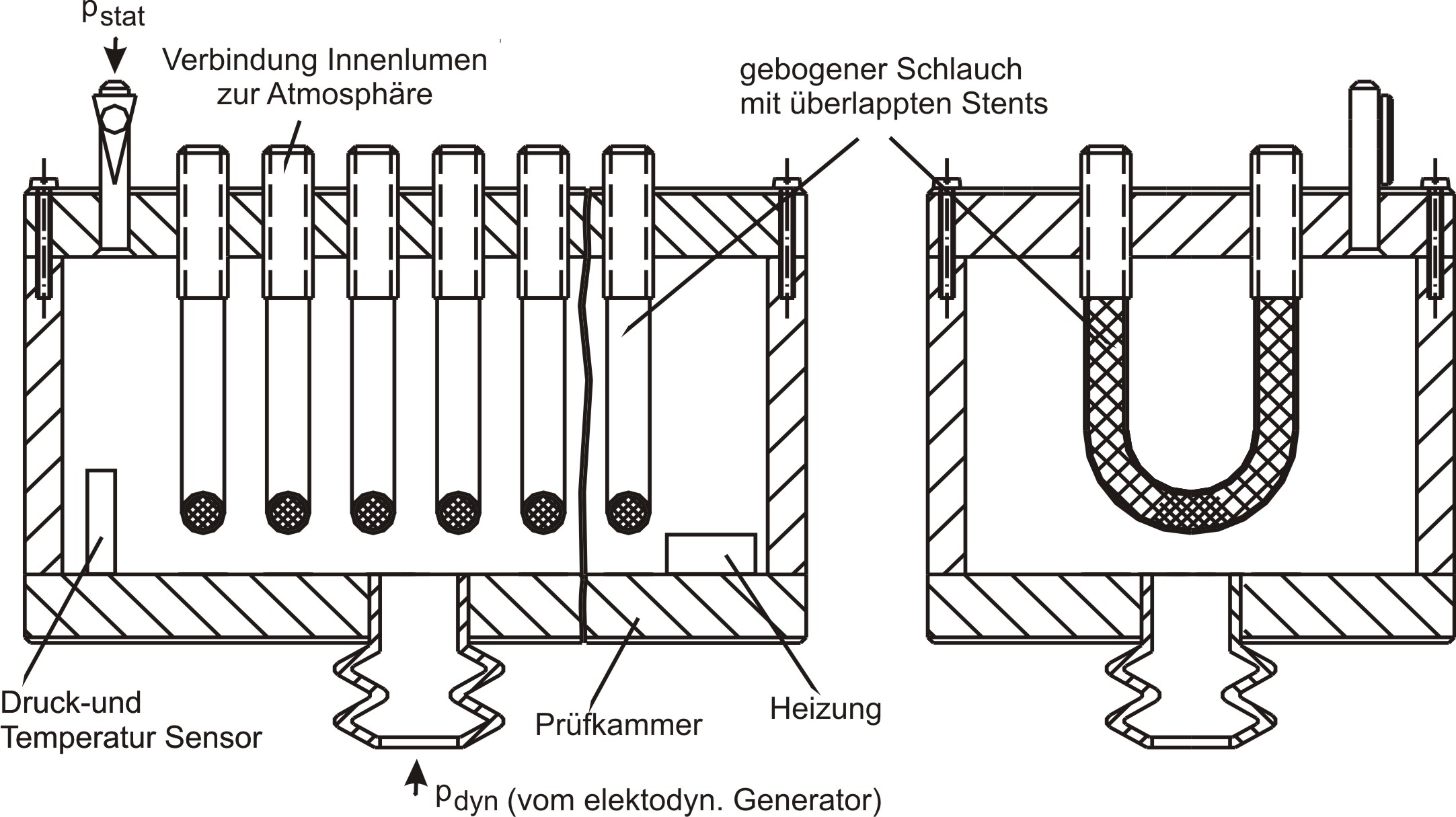
Measurement of the integral water permeability, water entry pressure, and maximum tolerable internal pressure of a vascular prosthesis
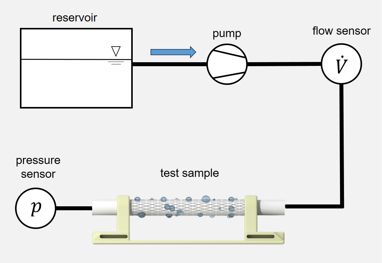
Normative reference of the test procedure:
DIN EN ISO 7198:2017, sect. 8.7.2.1.2, 8.7.2.1.4, A.5.1.3 A.5.1.4
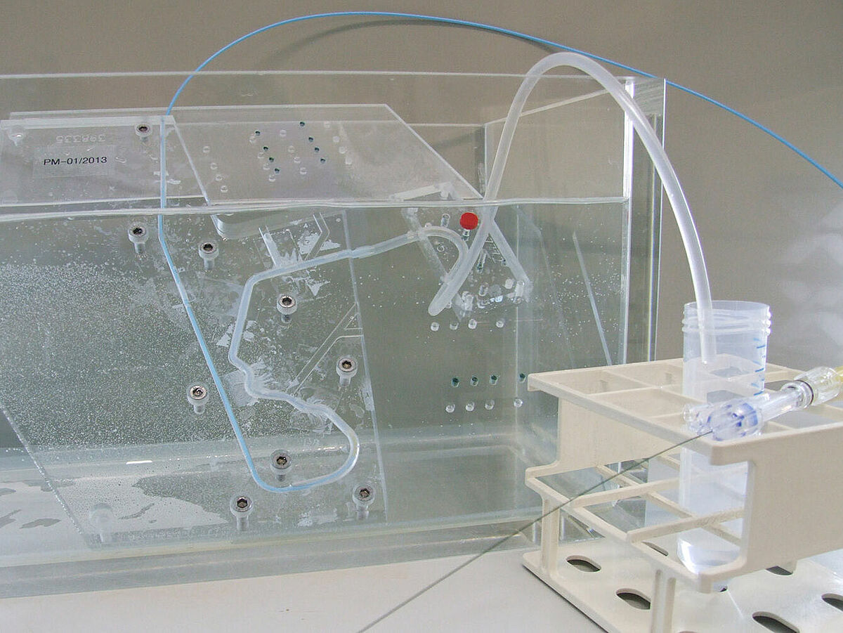
The test procedure covers determining the integral water permeability (at an internal pressure of 120 mmHg), water entry pressure, and maximum tolerable internal pressure of a (covered) vascular prosthesis. During application of a defined internal pressure the amount of water exiting per time unit through the outer wall of the (covered) vascular prosthesis is measured. This pressure is stepwise increased by 30 mmHg until the maximum tolerable internal pressure.
Peak tensile force of catheters
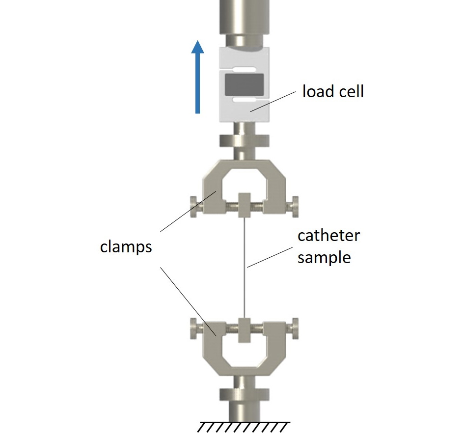
Normative reference of the test procedure:
ISO 10555-1:2023, sect. 4.9 and annex B
The peak tensile force of catheters is determined according to ISO 10555-1:2023, section 4.9 and Annex B. Tests may be conducted either on the complete catheter or on various (or relevant) catheter segments. The specimens are investigated in a uniaxial tensile test. The determined peak tensile forces are evaluated according to the minimum values defined in ISO 10555-1:2023.
